


When you see a screw size with an M followed by a number, that indicates the diameter of the threaded part (including the teeth) in millimetres. The corresponding imperial head size is also indicated.
The naming system allows engineers to quickly identify matching threaded components and facilitates streamlined procurement and assembly processes. The chart below shows the dimensions of common production screws.
Gauge
The gauge of a screw is a measure of the diameter of the threaded portion of the screw/bolt. It is important to understand that the diameter of a screw or bolt does not necessarily correlate with its length.
The word ‘gauge’ has a number of different meanings both as a verb and a noun, most relating to measurement. The noun form is used broadly, from measuring the thickness of wire (fine-gauge wire) to using a poll to gauge voter sentiment. The verb form also has many different uses, from throwing down a gage to challenge someone to combat to the use of a pressure gauge to check the air pressure in your car tires.
The spelling of the noun ‘gauge’ is often confused with the word ‘gage’. However, ‘gauge’ is the preferred spelling and is much more commonly used even in technical contexts. The spelling ‘gage’ appears to be mostly used in references to machinery and equipment, although it is also occasionally found in usage relating to measurements (for example, a pressure gauge). These two different meanings are reflected in the different spellings of the words.
Thread
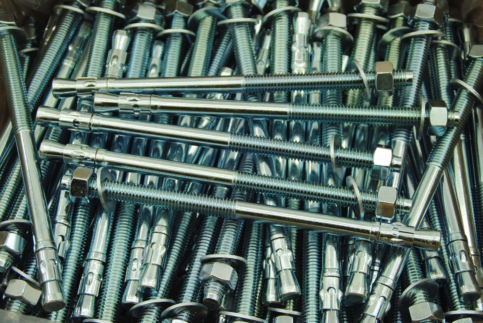
The thread of a screw or bolt is the series of grooves that the screw engages with its surrounding material. This is what actually transmits the tensile stress of the screw, so it’s important to ensure that this is made to appropriate dimensions.
The standard metric thread system uses a number (preceded by the letter M) that indicates the diameter of the threaded part of the screw, and the number after the M indicates the pitch, which is the distance between thread peaks in a one-inch length of the thread. This allows engineers to quickly identify a thread size and match it with mating components.
In contrast, the Unified Thread System is based on inches and has a different system for identifying screw sizes. Screw sizes are identified by their major diameter and the number of threads per inch. For example, a screw with a major diameter of 1/4″-20 has 20 threads per inch. This chart shows the corresponding diameter/pitch combinations for both systems.
Length
If a screw is intended to penetrate a thicker material, the length is important to consider. It must be sized such that the smooth part of the shank goes through the thinner material and the threaded portion extends into the thicker piece to ensure the screw is strong enough to hold its load.
Metric screw sizes are usually standardized to an ISO standard and designated using a combination of major diameter and thread pitch. For example, an M6 screw has a major diameter of 6 mm and a thread pitch of 1 mm. This naming convention allows engineers to quickly identify and match mating components, speeding up production and assembly times.
Screws can also be sized in an Imperial system which uses both the Gauge figure and the length. To help customers who work with both systems we have a handy table that converts the imperial measurements to the metric equivalent (see Imperial to Metric screw size chart).
Tolerances
It’s essential that a screw thread fits the thread of its matching nut. But perfect accuracy in producing both is not feasible, and that’s why a system of tolerances has been established for screw threads.
A tolerance number indicates the degree to which a thread can be deviated from its ideal profile without compromising its function. A wide tolerance is easier to produce but yields a larger spread between individual threads, while a narrow tolerance is harder to make but results in a smaller spread between individual threads.
A screw thread size is determined by its major diameter and its pitch, which is the distance between adjacent thread points. Its size is then indicated by a number pair consisting of the diameter-pitch designation, the tolerance class, and the thread type. For example, 6H/g6 indicates that the thread has a 6g tolerance class and an H female (internal) thread. This means the actual profile of the thread will be closer to the theoretical profile than a thread with no tolerance class would.