A fire pump is a pressure-increasing component of the water supply for fixed-place fire suppression systems. Fire pumps are crucial in high-rise structures and expansive spaces where water pressure from water mains or firefighters cannot reach.
A comprehensive driver/operator training program should teach the ideal pumping pressure for each standard hose deployment on the fireground.
Flow
Annual fire pump flow tests are an important part of maintaining a fire protection system. They help fire departments ensure that the fire pumps can deliver enough water to fight a fire quickly, and they also give technicians an opportunity to identify any problems with the system’s water supply. It’s important to use high-quality test equipment during these tests. The pressure gauges used during a test should be able to measure down to the nearest fraction of a percent, and they should bear a label attesting that they were calibrated within the past year by an approved calibration facility.
During a fire pump flow test, the AHJ (Authority Having Jurisdiction) will inspect the system’s capacity to deliver enough water for manual firefighting operations at 20 psi residual pressure. This water may come from fire hydrants on the property, or it may be supplied by an external source such as a municipal tanker shuttle service. The fire department can also test the performance of the fire pump by using a temporary tank or pond located on the site.
Fire pumps are rated by their manufacturers to produce a specific net pressure at a given flow, and this information is available in the form of a graph. The net pressure is plotted on the “x” axis or horizontal axis of a graph, and the flow is plotted on the “y” axis or vertical axis. Fire pump designers use the performance curves to determine a fire pump’s ability to provide a sufficient amount of water under various conditions.
A favorable fire pump flow test result is one that produces a downward slope on the graph. The graph should be evaluated and compared to the manufacturer’s original acceptance test results and the AHJ’s requirements to make sure that the pump is capable of delivering sufficient water at a fire alarm condition. During a fire pump flow test, it’s necessary to close any open pressure relief valves in the system, as they can impact the results by discharging water during the test.
During a fire pump flow test, hoses are connected to the pump’s discharge test header and run to a safe location where flowing water won’t cause damage. Those who are conducting the test should wear protective gear, be aware of the potential for flashover when using hoses, and only use hoses that have passed a previous flow test. T-shaped hose monsters that counteract the force of the water are safer to use than regular nozzles during testing.
Pressure
The pressure at which the fire pump operates is determined by its GPM (gallons per minute) and PSI (pressure per square inch). The higher the PSI, the more force the water has. Generally speaking, fire pumps operate at between 200 and 400 psi.
The fire pump is the heart of any firefighting apparatus. Located just behind the jump seat area, it is a large diesel engine-powered device that resembles a large rotor with curved blades. Driven by its own diesel engine, the pump creates high pressure by using an impeller to move water through it in a circular motion. As the water flows through, it is forced outward by centrifugal force. This force, or pressure, is what makes the water stream powerful enough to penetrate walls and other obstacles in a structure.
Often, fire pumps are used to fill booster tanks or to supply 60-gpm fog nozzles over long distances. However, they are also used to extinguish minor structural fires and fill pre-connected 1 3/4-inch lines.
Once a department conducts a flow test on its fire pump, it should then use the results to determine what the optimum hose line pressure is for each pre-established nozzle configuration on its fleet of fire apparatus. The process of friction-loss calculation will be the most time consuming and labor intensive part of this exercise, but it is critical that departments perform it as a standard operating procedure.
The optimum pressure for each hose line can be found by using the fire pump manufacturer’s curve and the corresponding nameplate data. For maximum accuracy, it is important that the fire pump’s nameplate and engine control modules match.
Once the optimum pressure has been determined, the fire department should set its engine’s governor to maintain this pressure. An electronic pressure governor is typically used to accomplish this goal, though manual governors can be used as well. These devices connect to the fire pump’s pressure transducer and adjust engine speed accordingly. A variety of EPGs are available to fire apparatus manufacturers, and they differ in terms of features, functionality and engine compatibility.
Design
The fire pump is the heart of a fire engine. It is located just behind the fire engine’s jump seats, and it is powered by a diesel engine. It is designed to be a very efficient machine, and its goal is to get water to the crew quickly. The pump works by creating water pressure through an impeller that is a rotor-like device with curved blades. The diesel engine spins the impeller at a very fast rate. As the impeller spins, it creates centrifugal force that pushes water forward at a very fast pace. As the water is pushed forward, it is pulled in to a valve that opens at the bottom of the pump. Once the water has reached this valve, it is sucked in and sent to the hard suction line.
Before water can be sucked into the hard suction line, it must first be primed. The operator flips an electronic switch on the pump panel to prime the line. Water is then pumped through the hard suction line and sucked into the fire engine. The pump operator then checks to see which lines have been pulled off of the tank, and he or she will discharge those lines. A plate below each lever on the fire pump panel indicates which lines are being sucked in and which ones have been discharged.
When determining the flow and pressure of a firefighting pump, it is important to consider the needs of each specific job. A fire may require a high GPM to move lots of water, or it may need a very high PSI to produce a lot of water pressure. In either case, the correct pump will be capable of meeting the requirements of the firefighting situation.
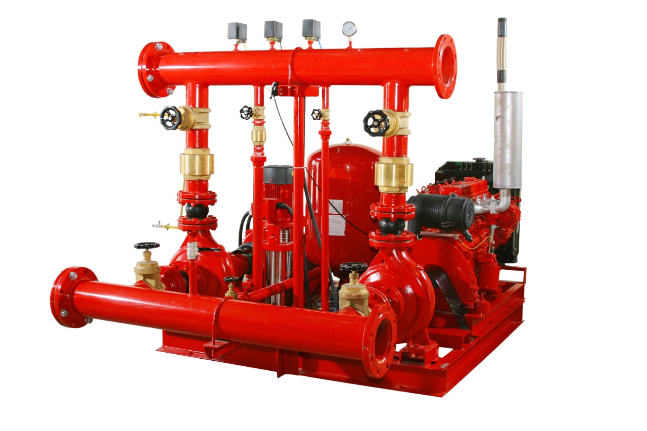
Many industrial plants use two or more fire pumps in order to ensure the plant’s safety in the event of a fire. Typically, the plants will use treated water for firefighting, but they also have facilities to store untreated water, such as that from a lake or sea, as a backup. Using six fire-water pumps (two electric motor-driven centrifugal pumps, two diesel engine-driven centrifugal pumps and two jockey pumps) is a common configuration for critical plants such as refineries and large chemical and petrochemical plants.
Maintenance
Fire pumps are critical components of water-based fire suppression systems. They must be inspected, tested and maintained regularly to ensure proper function during an emergency. While weekly inspections can be conducted by staff, dedicated fire safety professionals should perform monthly, annual and multi-year fire pump inspections and maintenance to help assure this vital piece of equipment will respond appropriately during an emergency.
The heart of a fire pump is the impeller water pump located on the top of the truck just behind the jump seat area. The pump is driven by the diesel engine and uses electricity to spin an impeller with curved blades. As the impeller spins, it creates high-pressure water by centrifugal force. This water is then pushed through the pump’s discharge valves and out of the hose line.
In addition to ensuring the right amount of water is available for the hose line, the MPO must also be able to determine the correct pressure for every pre-connected hose line on the apparatus. This requires memorizing and understanding an enormous amount of mathematical formulas and the ability to read and understand the metering system. Fortunately, today’s fire engines have made this much easier for the MPO by using digital display screens on the dashboard and computerized governors which automatically set the proper pressure.
Another important factor in fire pump performance is the pressure maintenance system, which consists of the hydraulic accumulator, jockey pump and control panel. The purpose of the accumulator is to keep the entire network of water lines for the fire suppression system fully pressurized. It does this by absorbing the loss of water flow to the fire suppression system while simultaneously maintaining a constant, balanced, discharge pressure.
Keeping a fire pump running at its best requires regular lubrication. This is especially true when the pump is in use at a fire scene, where it may run for long periods of time. A low oil level can cause the motor to overheat and can result in costly repairs.